Channels¶
Note
Scientific validation
The channel pipeline transformations and their immutable parameter record have been scientifically validated against published references. See the per-component reports:
Device fingerprint: validated with documented limitations.
TX power-amplifier nonlinearity (Rapp, Saleh): validated with documented limitations.
TX phase noise (Leeson): validated with documented limitations.
TX IQ imbalance, DAC quantization, CFO: validated.
AWGN channel propagation: validated.
RX mixer, IF filter, resampler: validated with documented limitations.
RX LNA noise, ADC quantization, AGC: validated with documented limitations.
RX phase noise and IQ imbalance: validated with documented limitations.
Each report covers construct validity, mathematical correctness against cited equations, empirical comparison to published reference numbers, literature grounding, experimental methodology, operating envelope, and documented limitations.
The channel pipeline is the “what happens over the air and inside the radios” part of a scene. Each emitter starts with clean complex baseband IQ, meaning in-phase/quadrature samples centered at 0 Hz while the real carrier frequency stays in metadata. The channel pipeline turns each clean emitted waveform into what each receiver records after transmit (TX) hardware effects, propagation through the environment, receive (RX) band selection, and RX hardware effects. The pipeline is organized as two semantic channel groups plus the receiver frontend, fifteen explicit transformations in all.
For a repeatable controlled chain, use a synthetic channel profile. A profile selects existing TX, propagation, and RX transformations in this same order and writes an immutable sweep manifest; it does not introduce a second channel model or claim calibration to a physical receiver.
Overview¶
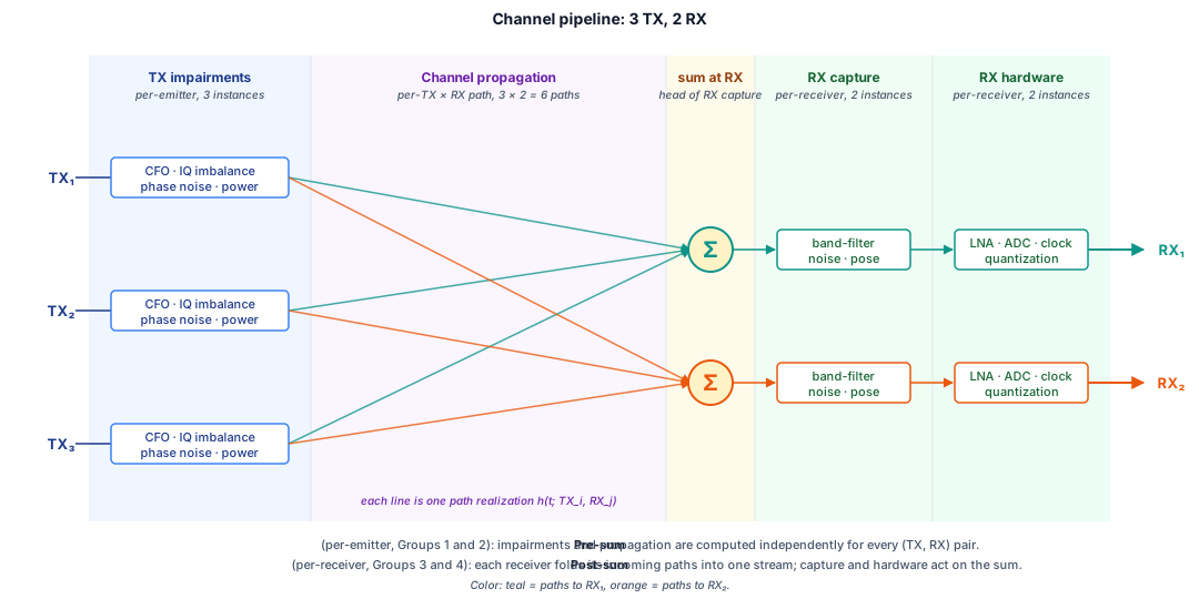
Channel pipeline with three transmitters and two receivers. TX impairments run per emitter at the requested scene/channel rate. A plugin that returns another rate is resampled to that rate before frequency placement and propagation; propagation then runs per path or, for a backend that supports it, on a summed receiver buffer. RX capture and RX hardware run post-sum, per receiver.¶
There are two pipeline groups, TX and CHANNEL, followed by the receiver, whose
nine transformations are identified by the Transformation.is_receiver
predicate rather than by a group. The receiver runs as one shared frontend
chain, split into a capture plane and a hardware plane:
TX impairments (per emitter, Group.TX): transmitter hardware effects before the signal enters the channel: digital-to-analog converter (DAC) quantization, power-amplifier (PA) nonlinearity, TX phase noise, TX IQ imbalance, and carrier frequency offset (CFO).
Channel propagation (per path or supported summed receiver buffer, Group.CHANNEL): one BaseChannel slot at the scene/channel rate. Sionna is the canonical physical-propagation route when a scenario needs distance loss, reflected paths, obstacle fading, or motion effects. AWGN is an explicit lightweight baseline for controlled noise tests, not the production recommendation.
RX capture (per receiver, post-sum), the receiver’s capture plane (
ReceiverStagePlane.CAPTURE): receiver LO frequency error, intended mixing into the receiver frequency frame, intermediate-frequency (IF) filtering, resampling to the receiver sample rate, and low-noise-amplifier (LNA) noise injection. This plane operates on the summed receiver stream.RX hardware (per receiver), the receiver’s hardware plane (
ReceiverStagePlane.HARDWARE): analog-to-digital converter (ADC) quantization, RX phase noise, RX IQ imbalance, and automatic gain control (AGC).
Source: the operation inventory is a summary of the four channel subpages. Those pages cite IEEE Std 1241-2010 and Analog Devices MT-001 for converter quantization, Rapp and Saleh for PA nonlinearity, Leeson for phase noise, Razavi, MathWorks, and Analog Devices for IQ imbalance, GNU Radio for carrier-frequency offset and receiver frequency translation, SciPy and Crochiere/Rabiner for resampling, Nyquist, Friis, and IEEE Std 145-2013 for receiver noise, MathWorks and liquid-dsp for AGC, and Sionna plus 3GPP TR 38.901 for channel propagation.
After scene frequency placement, each component carries its absolute carrier as
realized_carrier_hz in metadata; the composer derives it from the scene
center plus the relative placement offset. Each receiver resolves its effective
center_freq_hz, bandwidth_hz, and sample_rate_hz from ReceiverConfig when those fields are set, otherwise from the scene-level defaults on scene_cfg. Stored SceneMetadata does not duplicate those RF fields.
Pipeline overview¶
R_channel is SceneConfig.sample_rate_hz, the rate requested from every
emitter. A plugin can return a different R_emitter; the composer then
resamples it to R_channel after TX impairments and before
frequency placement/propagation. R_rx is the receiver sample rate after RX
capture resampling. Acronym-heavy
rows point to subpages where each operation is introduced with its API
slot and default backend.
Group or receiver plane |
Scope |
Sample rate |
Transformations |
Reference |
|---|---|---|---|---|
per emitter |
requested |
DAC quantization, PA nonlinearity, TX phase noise, TX IQ imbalance, CFO |
||
per emitter/RX or summed receiver buffer, by |
|
Channel propagation |
||
Receiver capture plane ( |
per RX, post-sum |
|
RX LO frequency error, RX mixer, IF filter, resampler, LNA noise |
|
Receiver hardware plane ( |
per RX |
|
ADC quantization, RX phase noise, RX IQ imbalance, AGC |
Per-transformation tables live on each sub-page. Each row carries the operation name, its Transformation enum member, the ABC, and the default backend.
Place In The System¶
The channel pipeline sits between scene composition and storage. The scene
composer assigns emitter positions, the final placed-component
realized_carrier_hz, and TX/RX antenna metadata. The channel pipeline
receives those assignments and produces one digitized capture per receiver.
The storage layer writes them as one record, each receiver its own subtree.
Emitters are upstream: they produce clean baseband IQ at the requested
scene/channel rate (or return a distinct rate that the composer normalizes)
before TX impairments run. Labels and annotations are downstream: they
read the placed-component metadata, including realized_carrier_hz, channel
profile parameters, and per-RX SNR estimates.
Boundaries¶
The channel pipeline owns:
Five TX transformations, one propagation transformation, and nine post-sum RX transformations.
The band-overlap predicate that selects which emitter components reach each receiver.
The sum of in-band propagated components at the head of RX capture.
Per-receiver routing of the post-sum signal through RX capture and RX hardware.
The channel pipeline does not own:
Baseband modulation and pulse shaping: emitter responsibility.
Carrier assignment and time placement: scene-composer responsibility.
Label generation and bounding boxes: labeler responsibility.
Record persistence: storage responsibility.
Sample-rate selection at the emitter: the composer requests the scene/channel rate. If a plugin returns another rate, the composer normalizes it to that rate; RX capture then resamples each receiver buffer to its effective RX rate.
Data Flow¶
The diagram shows the composed-scene order. An emitter first produces requested
scene-rate baseband IQ (or a plugin-returned rate); the composer writes its
final realized_carrier_hz only after TX impairments, any needed resampling,
and scene frequency placement. Receiver configs
provide the tuned center frequency, analog capture bandwidth, and sample rate
used for the band-overlap test and RX resampling.
        flowchart TD
    EMT["Emitter\n(clean requested-rate baseband)"]
    G1["TX impairments\nDAC · PA · TX-PN · TX-IQ · CFO\nper emitter"]
    RATE["Normalize plugin-returned rate\nR_emitter → R_channel if needed"]
    G2["Frequency placement + propagation\nSionna canonical; AWGN baseline\nper path or supported summed buffer"]
    SEL["Band-overlap select\nemitter.realized_carrier_hz in\nrx.center_freq_hz ± rx.bandwidth_hz/2"]
    G3["RX capture\nRX LO error · RX mixer · IF filter · resampler · LNA noise\nper RX, post-sum"]
    G4["RX hardware\nADC · RX-PN · RX-IQ · AGC\nper RX"]
    REC["One record\n(one digitized capture per RX + metadata)"]

    EMT --> G1 --> RATE --> G2 --> SEL --> G3 --> G4 --> REC
TX impairments are pre-sum and per emitter. The composer normalizes any
plugin-returned rate to the scene/channel rate before frequency placement and
propagation. Propagation runs
per path or, when the selected backend supports it, on the summed receiver
buffer according to scene.channel_application. RX capture and RX hardware are
per-receiver post-sum chains.
TorchSig refers to the external RFML benchmark library; its adapters are documented in TorchSig Interop.
Minimal Example¶
This is a full-contract skeleton, not the smallest quickstart path. Build a single ChannelPipeline carrying the six chain transformations plus the nine receiver stages, and pass it to the scene composer. The composer dispatches TX impairments per emitter, applies propagation according to scene.channel_application, then runs the nine receiver stages per receiver after the sum. Receiver entries are not chain entries: they are receiver-frontend stages held in receiver_stages alongside the chain.
import torch

from rfgen.core.pipeline import ChannelPipeline
from omegaconf import OmegaConf
from rfgen.config import from_hydra, validate_config
from rfgen.engine.propagation_sionna import SionnaUMi
from rfgen.receiver.stages.analog import (
    IQImbalanceStage,
    RXPhaseNoiseStage,
    ThermalNoiseStage,
)
from rfgen.receiver.stages.conversion import ADCQuantizerStage, AGCStage
from rfgen.receiver.stages.filtering import IFFilterStage, PolyphaseResamplerStage
from rfgen.receiver.stages.frequency import LOFrequencyErrorStage, MixerStage
from rfgen.scene import DefaultSceneComposer
from rfgen.hardware.tx import (
    LeesonTXPhaseNoise,
    LinearCFO,
    LinearDACQuantizer,
    RappPA,
    LinearTXIQImbalance,
)

channel = ChannelPipeline(
    [
        # TX impairments (per emitter, pre-sum)
        LinearDACQuantizer(enob_bits=14),
        RappPA(),                     # Rapp model default
        LeesonTXPhaseNoise(),         # Leeson model default
        LinearTXIQImbalance(),
        LinearCFO(f_offset_hz=250.0),
        # Canonical urban-micro physical propagation. The complete scene config
        # supplies typed topology and selects `channel_application: per_emitter`.
        SionnaUMi(),
    ],
    receiver_stages=[
        # Capture plane (per receiver, post-sum)
        LOFrequencyErrorStage(frequency_error_hz=125.0),
        MixerStage(),
        IFFilterStage(cutoff_norm=0.4, num_taps=65, gain=1.0),
        PolyphaseResamplerStage(up=1, down=1),
        ThermalNoiseStage(noise_figure_db=5.0),
        # Hardware plane (per receiver, post-sum)
        ADCQuantizerStage(enob_bits=10),
        RXPhaseNoiseStage(),
        IQImbalanceStage(),
        AGCStage(),
    ],
)

composer = DefaultSceneComposer()
scene_signal = composer.build(
    scene_cfg=from_hydra(OmegaConf.load("configs/config.yaml")).scene,
    emitter_pool=emitter_pool,  # supplied by the emitter setup code
    channel=channel,
    rng=torch.Generator().manual_seed(0),
)
Load Hydra-managed configs through from_hydra() or validate plain dict payloads through validate_config(), then pass the resolved cfg.scene into the composer. This illustrative chain is only complete when the scene configuration supplies Sionna’s typed TX/RX topology, positive absolute carrier, and channel_application: per_emitter, and the emitter/setup supplies SignalMetadata.tx_power_dbm; see Sionna integration and Scene API. See Reference / Scene Composition Algorithm § Frequency placement strategies for how dense-band scenarios place emitters.
Each receiver’s effective center_freq_hz, bandwidth_hz, and sample_rate_hz come from the ReceiverConfig entry when that field is set, otherwise from scene_cfg.center_hz, scene_cfg.bandwidth_hz, and scene_cfg.sample_rate_hz. ReceiverConfig does not carry an rx_chain override; the post-sum path comes from the receiver entries in channel, which the pipeline holds as receiver-frontend stages split across the capture and hardware planes. See Reference / Scene Composition Algorithm for the full dispatch contract.
Design Notes¶
Sample rate hierarchy¶
The composer requests R_channel = SceneConfig.sample_rate_hz from each
emitter, where TX impairments run. A plugin that returns R_emitter instead is
resampled to R_channel before frequency placement and channel propagation.
RX capture then filters and resamples the summed receiver buffer
from R_channel to R_rx, and RX hardware remains at R_rx. Each receiver
may have a different R_rx; SceneConfig.sample_rate_hz is the channel-rate
and construction-time default, not a stored scene-metadata field.
Why one channel propagation slot¶
Sionna scenario backends are the canonical physical-propagation route: they can realize coupled path loss, multipath, shadowing, and Doppler in a per-emitter/RX path; TDL/CDL instead provide controlled link-level fading profiles. See Sionna integration. AWGNChannel is retained as an explicit lightweight baseline for controlled noise tests. The current geometry-free runtime still selects that baseline unless a Sionna backend is configured, an implementation gap documented in the Sionna integration. Splitting a selected propagation model into multiple pipeline slots would require rfgen to orchestrate its internal state. The chosen scene.channel_application mode determines whether a backend runs per path or, when supported, on the summed receiver buffer.
Source: Channel propagation cites Sionna’s TR 38.901 UMa, UMi, RMa, TDL, CDL, and RT implementations, plus the underlying ETSI TR 138 901 / 3GPP TR 38.901, for the one-slot propagation contract.
ChannelPipeline aggregator¶
ChannelPipeline is the
Container that collects the full transformation chain and
enforces its structural invariants before any DSP runs. The pipeline
carries no signal-processing code; it holds an ordered
tuple[BaseChannel, ...] plus an ordered receiver_stages tuple, and
exposes the partitioned views the scene composer reads at dispatch time.
Why a separate aggregator. Putting the chain in a dedicated validated object means errors in chain ordering surface at construction time, not partway through a scene generation run. Plugin authors who assemble a chain from config get the same validation as authors who write Python directly.
Group-partition rule. The two chain partition properties
(tx_transforms, propagation) split the chain by
Group using each entry’s
transformation.value // 10. Group values are assigned in multiples of
10 so that the integer floor division maps cleanly onto the group
names without ambiguity between groups. The receiver is partitioned
separately: receiver_stages holds every configured receiver stage in
order, and capture_plane_stages and hardware_plane_stages split
those by ReceiverStagePlane, which is where the composer runs the
joint receiver-background injection.
Immutability contract. ChannelPipeline is a frozen dataclass and
stores the chain as a tuple. Two mutation attempts are pinned:
pipeline.chain[i] = otherraisesTypeErrorbecause tuples are immutable.pipeline.chain = (...)raisesdataclasses.FrozenInstanceErrorbecause the dataclass is frozen.
Both paths are exercised by the contract tests.
Validation invariants. The following are checked at construction:
Every chain entry is a BaseChannel instance, and a receiver transformation in the chain is rejected: it belongs in
receiver_stages.Group order is monotonic non-decreasing on
transformation.groupalong the chain (TX before CHANNEL).Within a group,
transformationordinals are monotonic non-decreasing (the canonical per-group ordering).At most one Group.CHANNEL propagation entry is present.
Every
receiver_stagesentry is aBaseReceiverStageinstance, and no capture-plane stage follows a hardware-plane one.
A violation raises ChannelError with a message that names the offending pair, so the configuration author can correct the chain without reading the validator source.
An empty chain and a chain missing any particular group both pass validation; the scene composer documents which groups it requires.
Config-driven construction. ChannelPipeline.from_config(config: ChannelChainConfig) resolves each chain entry through
EntryPointRegistry under the
rfgen.channels entry-point group. The discovered class is
instantiated with the entry’s params mapping forwarded as keyword
arguments, then the full validated chain is built via the standard
constructor. Config-time and code-time construction therefore enforce
the same invariants.
ChannelChainConfig is an alias
for ChannelConfig (the Pydantic model). No separate config class is used.
See Reference / rfgen.core.pipeline for the full
parameter surface, field schemas, method signatures, and error
contracts.
Explicit transformations everywhere else¶
TX impairments, RX capture, and RX hardware use explicit plugin slots instead of a single opaque impairment object. This makes each effect replaceable independently, keeps the metadata contract auditable at each step, and supports ablation studies that disable one transformation without touching others.
See Also¶
TX impairments: DAC, PA, phase noise, IQ imbalance, CFO.
Channel propagation: Sionna-backed propagation slot and per-pair propagation semantics.
RX capture: mixing, filtering, resampling, summing, and LNA noise.
RX hardware: ADC, RX phase noise, RX IQ imbalance, AGC.
Coordinate Systems § Frequency Frames: how
realized_carrier_hz(metadata) becomes a sample-domain shift at the RX mixer.Reference /
rfgen.core.pipeline: full parameter surface, schemas, and method signatures.Sionna integration: optional propagation and ray-tracing boundary.
Background / Design Decisions § Channel pipeline for the rationale behind the semantic-group, fourteen-transformation redesign and why the prior five-stage chain was retired.