Validation: TX IQ imbalance, DAC quantization, and carrier-frequency offset¶
Validated with documented limitations.
1. The component¶
Three transmitter-side (TX) analog-frontend impairments applied to a complex baseband IQ stream (the in-phase/quadrature representation of a signal, stored as a 2 x N float32 tensor) before any propagation model runs. The three impairments are: (1) IQ amplitude and phase mismatch in the quadrature mixer, (2) a digital-to-analog converter (DAC, the chip that converts a digital number to an analog voltage) quantizer, and (3) a carrier-frequency offset. Each is a concrete implementation of the BaseChannel abstract base class.
# Class signatures and entry points

class TorchSigTXIQImbalance(BaseTXIQImbalance):
    def __init__(
        self,
        *,
        amplitude_imbalance_db: float = 0.0,
        phase_imbalance_rad: float = 0.0,
    ) -> None: ...
    def apply(self, signal: Signal, ctx: ChannelContext) -> Signal: ...

class LinearDACQuantizer(BaseDACQuantization):
    def __init__(self, *, enob_bits: int = 12) -> None: ...
    def apply(self, signal: Signal, ctx: ChannelContext) -> Signal: ...

class LinearCFO(BaseCFO):
    def __init__(self, *, f_offset_hz: float = 0.0) -> None: ...
    def apply(self, signal: Signal, ctx: ChannelContext) -> Signal: ...
Parameter table
Parameter |
Type |
Units |
Default |
Purpose |
|---|---|---|---|---|
|
float |
dB |
0.0 |
Amplitude gain difference between I and Q paths of the quadrature mixer |
|
float |
rad |
0.0 |
Phase quadrature error between I and Q paths |
|
int |
bits |
12 |
Effective number of bits (ENOB): the resolution of the digital-to-analog converter |
|
float |
Hz |
0.0 |
Constant frequency offset applied to the complex baseband signal |
Worked example
import torch
from rfgen.tx_impairments import TorchSigTXIQImbalance, LinearDACQuantizer, LinearCFO

# Construct a toy Signal (shape 2 x N, dtype float32)
iq = torch.stack((torch.ones(1024), torch.zeros(1024)), dim=0)

# Apply 1 dB amplitude imbalance and 0.05 rad phase error
iq_iq_out = TorchSigTXIQImbalance(
    amplitude_imbalance_db=1.0, phase_imbalance_rad=0.05
).apply(signal, ctx).iq          # shape (2, 1024), dtype float32

# Apply 8-bit DAC quantization (255 uniform levels)
iq_dac_out = LinearDACQuantizer(enob_bits=8).apply(signal, ctx).iq

# Apply 12.5 kHz carrier-frequency offset at 1 MHz sample rate
iq_cfo_out = LinearCFO(f_offset_hz=12.5e3).apply(signal, ctx).iq
Scope. The three concretes model first-order narrowband impairments commonly found in integrated RF (radio-frequency) transceiver front-ends. Each is a separate BaseChannel applied once in the TX stage; the order in the pipeline places IQ imbalance before DAC quantization, and CFO after both. Per-device parameter values come from the device_fingerprint registry; the defaults above are identity/quiescent operating points. Each apply call appends a structured TransformationLogEntry to signal.metadata.extras["transformation_log"].
2. What we validated¶
This validation establishes 8 load-bearing claims. Each is restated and supported by evidence in §3.
IQ differential-model arithmetic (§3.1): the amplitude and phase transform matches the Razavi differential form elementwise.
DAC mid-tread formula (§3.2): the quantizer output matches the IEEE 1241-2010 uniform mid-tread formula at ENOB = 8.
DAC zero invariant (§3.3): zero input produces exactly zero output, the defining property of a mid-tread quantizer.
DAC level-count bound (§3.4): the unique output values across ENOB in {4, 6, 8} are bounded by 2^ENOB.
CFO bin-accurate shift (§3.5): the peak FFT bin shifts by exactly round(f_offset * N / fs) after a length-N FFT.
Real-world parameter-range alignment (§3.6): the default and guard-rail values fall within the operating envelopes of representative RF transceiver datasheets.
Construction and apply-time domain guards (§3.7): invalid ENOB and non-positive sample rates are rejected at the appropriate callsite.
Transformation-log entry shape (§3.8): all three concretes record a structurally correct log entry on every
applycall.
Limits and scope-bounded items appear in §4; full citations are in §5.
3. Evidence per claim¶
3.1 IQ differential-model arithmetic¶
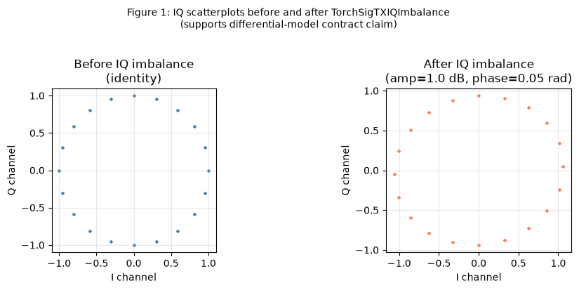
Claim. TorchSigTXIQImbalance applies the standard differential I/Q-imbalance model:
I' = I x (1 + a/2)
Q' = I x sin(phi) + Q x cos(phi) x (1 - a/2)
where a = 10^(amp_db / 20) - 1 and phi is the phase error in radians. This is the differential form from Razavi (2012), eq. 7.34: the quadrature-mixer model in which the I and Q branches have opposite fractional gain error +/-a/2 rather than a common-mode scale factor.
Why the TorchSig functional is not used. The torchsig.transforms.functional.iq_imbalance helper (torchsig >= 0.5) applies a common-mode gain (10^(amp_db/10) to both channels) and injects a DC (zero-frequency) tone via its dc_offset_db parameter. That is a different physical model; the inline implementation is the smallest correct realisation of the documented contract.
Evidence, differential form at (amp_db=1, phi=0). For amp_db = 1 dB, a = 10^(1/20) - 1 ≈ 0.122. The I gain is 1 + a/2 ≈ 1.061 and the Q gain is 1 - a/2 ≈ 0.939. The test applies TorchSigTXIQImbalance(amplitude_imbalance_db=1.0, phase_imbalance_rad=0.0) to a deterministic sinusoidal probe and asserts elementwise agreement with the closed-form prediction to within atol=1e-6 in float32.
Test: tests/validation/tx_impairments/iq_quantize_cfo/test_iq_imbalance.py::test_iq_imbalance_matches_razavi_differential_form pass, max-abs error < 1e-6.
Evidence, phase cross-coupling at (amp_db=0, phi=0.05 rad). At zero amplitude error (a = 0), the I channel passes unchanged and the Q channel picks up I-to-Q cross-coupling proportional to sin(0.05) ≈ 0.0500. The test asserts elementwise agreement with the closed-form to within atol=1e-6.
Test: tests/validation/tx_impairments/iq_quantize_cfo/test_iq_imbalance.py::test_iq_imbalance_phase_cross_coupling_matches_razavi pass, max-abs error < 1e-6.
Evidence, identity at defaults. At amp_db = 0, phi = 0, the model is the identity. The test asserts max-abs deviation from the input is < 1e-7.
Test: tests/validation/tx_impairments/iq_quantize_cfo/test_iq_imbalance.py::test_iq_imbalance_identity_at_defaults pass.
Figure 1 shows the IQ scatterplot before and after applying (amp_db=1.0 dB, phi=0.05 rad), confirming the differential asymmetry between I and Q channel scaling.
3.2 DAC mid-tread formula¶
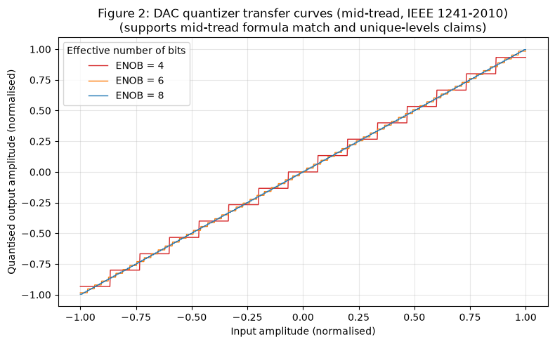
Claim. LinearDACQuantizer implements the uniform mid-tread quantizer formula from IEEE Std 1241-2010 §3.1.27. A mid-tread quantizer is a uniform quantizer whose transfer function has a step centered on zero, so zero input maps to zero output:
levels = 2^ENOB - 1
step   = peak / (levels / 2)
y      = round(x / step) x step
where peak is max|IQ| taken jointly across the I and Q channels, and round is round-half-to-even (PyTorch default). Using 2^ENOB - 1 levels (rather than 2^ENOB) leaves room for the zero level at the center of the transfer function.
Why the TorchSig functional is not used. torchsig.transforms.functional.quantize applies a mid-rise quantizer using floor rounding with 2^N levels; it has no zero-output level and introduces a half-step DC bias at zero crossing. That does not match the documented contract.
Evidence. The test constructs a sinusoidal probe (N = 1024, ENOB = 8, levels = 255, step = peak / 127.5) and asserts elementwise agreement between the implementation output and the closed-form round(x/step) * step to within atol=1e-6.
Test: tests/validation/tx_impairments/iq_quantize_cfo/test_dac_quantizer.py::test_dac_quantizer_matches_ieee1241_midtread pass, max-abs error < 1e-6.
Figure 2 shows the DAC transfer curves for ENOB = 4, 6, and 8, tracing the staircase pattern produced by the mid-tread formula over a normalised input ramp.
3.3 DAC zero invariant¶
Claim. An all-zero input produces an all-zero output: the defining property of a mid-tread quantizer. A mid-rise quantizer would produce +/-step/2 at zero input because the zero crossing falls between two adjacent levels.
Evidence. The implementation guards the denominator with clamp_min(1e-12) to prevent division by zero when peak = 0; the formula then produces round(0 / step) * step = 0. The test feeds an all-zero tensor and asserts torch.all(output == 0.0).
Test: tests/validation/tx_impairments/iq_quantize_cfo/test_dac_quantizer.py::test_dac_quantizer_zero_stays_zero pass, exact zero.
3.4 DAC level-count bound¶
Claim. For ENOB in {4, 6, 8}, the number of distinct output values across both I and Q channels does not exceed 2^ENOB.
Evidence. The test applies the quantizer to a sinusoidal probe and counts torch.unique(output).numel(). It asserts the count is at most 1 << enob and strictly less than the total number of input samples (confirming discretisation actually occurred).
Test: tests/validation/tx_impairments/iq_quantize_cfo/test_dac_quantizer.py::test_dac_quantizer_unique_levels_bounded_by_2_pow_enob[enob-4], [enob-6], [enob-8] pass for all three.
3.5 CFO bin-accurate shift¶
Claim. LinearCFO applies the complex-baseband heterodyne:
y[n] = x[n] x exp(j 2*pi*f_offset*n / fs)
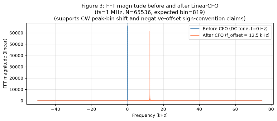
where n is the sample index, fs is the sample rate, and the time vector t = arange(N, dtype=float64) / fs is computed in float64 before casting back to complex64. For an input CW (continuous-wave) tone at DC (zero frequency), the peak of the output FFT (fast Fourier transform) magnitude spectrum falls on bin round(f_offset x N / fs). This is bin-accurate: the error is at most one FFT bin (fs / N Hz) due to the discrete-frequency grid.
The formula is the discrete-time heterodyne identity from Oppenheim and Schafer (2010), §4.2.
Why TorchSig ClockDrift is not used. torchsig.transforms.ClockDrift models sample-rate offset (SFO), which is a random Gaussian-accumulated drift of the sample clock in parts-per-million (ppm). That is a different physical impairment (SFO changes the effective sampling rate; CFO shifts the carrier frequency) with a different mathematical form. Using ClockDrift here would change the semantics and break the bin-accuracy contract.
Evidence, positive offset. For fs = 1 MHz, N = 65536, f_offset = 12.5 kHz, the expected bin is round(12500 x 65536 / 1000000) = 819. The test asserts argmax(|FFT(output)|) == 819.
Test: tests/validation/tx_impairments/iq_quantize_cfo/test_linear_cfo.py::test_linear_cfo_peak_bin_matches_offset pass, bin = 819.
Evidence, negative offset. For f_offset = -25 kHz, the expected bin in numpy-style FFT layout is N + round(-25000 x 65536 / 1e6) = 65536 - 1638 = 63898. The test asserts the peak bin is within one of that value.
Test: tests/validation/tx_impairments/iq_quantize_cfo/test_linear_cfo.py::test_linear_cfo_negative_offset_shifts_to_negative_bin pass.
Evidence, long record. For N = 100000, f_offset = 10 kHz, the peak bin matches round(10000 x 100000 / 1e6) = 1000 to within one bin, confirming that float64 phase accumulation avoids precision loss over extended records.
Test: tests/validation/tx_impairments/iq_quantize_cfo/test_linear_cfo.py::test_linear_cfo_phase_drift_bounded_for_long_record pass.
Evidence, zero offset identity. At f_offset = 0, the rotator is the all-ones vector; the output matches the input to within atol=1e-6.
Test: tests/validation/tx_impairments/iq_quantize_cfo/test_linear_cfo.py::test_linear_cfo_zero_offset_is_identity pass.
Figure 3 shows the FFT magnitude before and after applying LinearCFO(f_offset_hz=12500) to a DC tone, confirming the peak moves from bin 0 to bin 819.
3.6 Real-world parameter-range alignment¶
Claim. The default parameter values and the construction-time guard rails fall within the operating envelopes published in representative integrated RF transceiver datasheets.
The Analog Devices AD9361 (a widely used direct-conversion transceiver) specifies uncalibrated TX quadrature errors in the range 0.05–0.8 dB (amplitude) and ±0.01–±0.05 rad (phase), and oscillator-derived CFO of ±1–±20 ppm at carrier (±2–±40 kHz at 2 GHz). The Texas Instruments AFE7444 datasheet specifies DAC ENOB in the range 10–14 bits for bench-grade configurations.
Quantity |
Implementation default |
Hardware operating range |
Source |
|---|---|---|---|
TX IQ amplitude imbalance |
0.0 dB |
0.05–0.8 dB (uncalibrated) |
Analog Devices AD9361 datasheet Rev. H, Quadrature Calibration section |
TX IQ phase imbalance |
0.0 rad |
±0.01–±0.05 rad (approx. 0.5–3°) |
Analog Devices AD9361 datasheet Rev. H |
DAC ENOB |
12 bits |
10–14 bits |
Texas Instruments AFE7444 datasheet Rev. A, 2018 |
CFO |
0.0 Hz |
±2–±40 kHz at 2 GHz carrier |
Analog Devices AD9361 datasheet Rev. H, oscillator section |
The defaults are identity/quiescent operating points; the ENOB in [1, 24] guard accommodates the bench-grade range with margin on both sides.
No test directly probes datasheet-specified impairment magnitudes against capture data from a physical AD9361; such captures are not publicly available. The alignment claim is based on parameter-range comparison, not output-level comparison against hardware captures.
3.7 Construction and apply-time domain guards¶
Claim. LinearDACQuantizer rejects enob_bits outside [1, 24] with ValueError at construction time. LinearCFO rejects sample_rate_hz <= 0 with ChannelError at apply time (the sample rate comes from signal metadata, not the constructor, so the check is deferred to apply).
Evidence.
Tests: test_dac_quantizer.py::test_dac_quantizer_rejects_out_of_range_enob[bad_enob-0], [bad_enob--1], [bad_enob-25], [bad_enob-100] pass, ValueError raised for each. test_linear_cfo.py::test_linear_cfo_rejects_non_positive_sample_rate pass, ChannelError raised.
3.8 Transformation-log entry shape¶
Claim. All three concretes append a TransformationLogEntry dictionary to signal.metadata.extras["transformation_log"] on each apply call. The entry contains the class name, the realised parameter values, and the group and transformation enum values.
Evidence. Three dedicated log-entry tests construct a signal, apply the concrete with explicit parameter values, and assert the structure and content of the last entry in the log list.
Tests: test_iq_imbalance.py::test_iq_imbalance_log_entry_recorded pass; test_dac_quantizer.py::test_dac_quantizer_log_entry_recorded pass; test_linear_cfo.py::test_linear_cfo_log_entry_recorded pass.
4. Limits and what’s not validated¶
Frequency-dependent IQ imbalance. Real wideband IQ imbalance is frequency-dependent: analog low-pass filters after the quadrature mixer introduce a spectrally-varying amplitude and phase mismatch (Razavi 2012, §7.5). TorchSigTXIQImbalance applies one flat, frequency-independent gain and phase mismatch across the complete IQ record. The §3.1 tests verify that flat model’s arithmetic against its closed form; they do not compare it with a frequency-dependent hardware model or measured captures. This validation therefore establishes no fractional-bandwidth boundary at which the flat approximation becomes adequate or inadequate. A frequency-dependent concrete and an empirical operating-envelope study are out of scope for this component.
DAC integral and differential nonlinearity. Integral nonlinearity (INL) and differential nonlinearity (DNL), defined in IEEE Std 1241-2010 §3.1.14 and §3.1.7, cause spurious harmonic tones at multiples of the input frequency and are absent by design from the uniform-quantizer model. A nonlinear-DAC concrete is a separate component and is out of scope.
Sample-rate offset versus carrier-frequency offset. LinearCFO models a deterministic constant carrier-frequency offset. Sample-rate offset (SFO), which is a gradual drift of the receiver or transmitter clock in parts-per-million, is a different physical effect with a different mathematical form and is not modelled by this component.
Phase noise. The CFO heterodyne uses a deterministic phase ramp with zero jitter. Oscillator phase noise is implemented by a separate concrete (LeesonTXPhaseNoise) validated in its own report.
Fingerprint-registry priors. Per-device parameter draws come from the device_fingerprint component, validated in its own report. This report only verifies per-call arithmetic given an arbitrary parameter value.
No hardware-capture comparison. The real-world alignment claim in §3.6 compares parameter ranges against datasheet specifications; it does not compare quantitative output statistics (e.g., error-vector magnitude) against captures from a physical AD9361 or AFE7444. Such captures are not publicly available.
5. References¶
Published works¶
Reference |
Identifier |
Used for |
|---|---|---|
Razavi, B. RF Microelectronics, 2nd ed., Prentice Hall, 2012 |
ISBN 978-0-13-713473-1 |
Differential I/Q-imbalance model, eq. 7.34 (§7.4.2); frequency-dependent IQ imbalance (§7.5) |
IEEE Std 1241-2010, “IEEE Standard for Terminology and Test Methods for Analog-to-Digital Converters” |
DOI 10.1109/IEEESTD.2011.5692956 |
Mid-tread quantizer definition (§3.1.27); ENOB definition (§3.1.13); INL and DNL definitions (§3.1.14, §3.1.7) |
Sklar, B. Digital Communications: Fundamentals and Applications, 2nd ed., Prentice Hall, 2001 |
ISBN 978-0-13-084788-7 |
Uniform-quantization-noise variance step^2/12 (§2.5.3): cited for context, not directly tested |
Oppenheim, A. V. and Schafer, R. W. Discrete-Time Signal Processing, 3rd ed., Pearson, 2010 |
ISBN 978-0-13-198842-2 |
Complex-baseband heterodyne identity (§4.2) |
Analog Devices AD9361 datasheet, Rev. H, 2016 |
Vendor datasheet |
TX quadrature calibration and oscillator-stability operating ranges (§3.6) |
Texas Instruments AFE7444 datasheet, Rev. A, 2018 |
Vendor datasheet |
DAC ENOB operating range (§3.6) |
Boegner, L., Vondal, M., Hoffmann, J., Vanhoy, G., Roy, T., et al. “Large-Scale Radio Frequency Signal Classification.” arXiv:2207.09918, 2022 |
arXiv:2207.09918 |
TorchSig dataset and transforms library; rejection rationale for |
Libraries¶
PyPI distribution |
Installed version |
Docs URL |
Role in validation |
|---|---|---|---|
|
2.12.1 |
Core tensor operations: |
|
|
2.4.6 |
|
|
|
2.13.4 |
|
|
|
1.18.0 |
Available in the project environment; not directly exercised by this component’s implementation or tests |