Scientific validation: receiver front-end mixer, IF filter, and resampler chain¶
Validated with documented limitations.
1. The component¶
The rx_frontend/mixer_filter_resample component implements three deterministic-linear stages applied in sequence to a captured RF (radio-frequency, a signal transmitted wirelessly at some carrier frequency) signal entering an SDR (software-defined radio, a radio whose signal processing is performed in software rather than dedicated hardware) receiver:
Downconversion mixer (
LinearRXMixer): shifts energy at the RF carrier frequency down to baseband (DC, meaning zero frequency), making further digital processing frequency-agnostic. The signal is represented as IQ (in-phase and quadrature, the two real-valued components of a complex baseband signal) samples.IF filter (
ScipyFIRIFFilter): applies a linear-phase FIR (finite-impulse-response, a digital filter that computes each output sample as a weighted sum of a finite window of past input samples) low-pass filter at the IF (intermediate frequency, a shifted copy of the signal at a convenient frequency for digital filtering) stage to suppress energy outside the desired band.Polyphase resampler (
ScipyPolyResampler): changes the sample rate by a rational ratio (up/down), adjusting the representation to the downstream consumer’s required rate.
These three operations collectively model the DDC (digital downconverter, the block in an SDR receive chain that converts a digitised RF stream to a lower-rate baseband representation) of a software-defined radio receiver.
Signatures¶
class LinearRXMixer:
    def __init__(self) -> None: ...
    def apply(self, signal: Signal, ctx: ChannelContext) -> Signal: ...

class ScipyFIRIFFilter:
    def __init__(
        self,
        *,
        cutoff_norm: float = 0.4,   # normalised to Nyquist; (0, 1)
        num_taps: int = 65,          # must be odd and >= 3
        gain: float = 1.0,
    ) -> None: ...
    def apply(self, signal: Signal, ctx: ChannelContext) -> Signal: ...

class ScipyPolyResampler:
    def __init__(self, *, up: int = 1, down: int = 1) -> None: ...
    def apply(self, signal: Signal, ctx: ChannelContext) -> Signal: ...
Parameter table¶
Name |
Type |
Units |
Default |
Purpose |
|---|---|---|---|---|
|
|
fraction of Nyquist |
0.4 |
FIR low-pass cutoff, normalised to Nyquist (0.5×f_s) |
|
|
n/a |
65 |
Number of FIR coefficients; must be odd for linear phase |
|
|
linear |
1.0 |
Per-instance scalar applied between FIR design and FIR application |
|
|
n/a |
1 |
Upsampling factor (must be >= 1) |
|
|
n/a |
1 |
Downsampling factor (must be >= 1) |
Worked example¶
from rfgen.rx_frontend import LinearRXMixer, ScipyFIRIFFilter, ScipyPolyResampler
from rfgen.channels.protocols import ChannelContext, ChannelRxParams
from rfgen.core_types import Signal, SignalMetadata
import torch

# Minimal signal: 4096 float32 IQ samples at 1 MHz, carrier at 2.4 GHz
iq = torch.randn(2, 4096, dtype=torch.float32)
md = SignalMetadata(..., sample_rate_hz=1e6, realized_carrier_hz=2.4e9 + 200e3, ...)
sig = Signal(iq=iq, metadata=md)
ctx = ChannelContext(rx_params=ChannelRxParams(center_freq_hz=2.4e9, ...), ...)

out = LinearRXMixer().apply(sig, ctx)
# out.iq.shape == (2, 4096), dtype == float32
# out.metadata.realized_carrier_hz == 2.4e9  (updated to rx center)

out = ScipyFIRIFFilter(cutoff_norm=0.4, num_taps=65).apply(out, ctx)
# out.iq.shape == (2, 4096)

out = ScipyPolyResampler(up=1, down=2).apply(out, ctx)
# out.iq.shape == (2, 2048)
# out.metadata.sample_rate_hz == 5e5  (halved)
Each apply call appends a structured log entry to signal.metadata.extras["transformation_log"] recording the class name, group (RX_CAPTURE), transformation enum, and parameters used.
The component is scoped to the deterministic-linear subset of the receive chain. Stochastic impairments (thermal noise, quantization, ADC bit-depth effects, phase noise, IQ imbalance, AGC dynamics) are handled by separate components and are not exercised here.
2. What we validated¶
This validation establishes 9 load-bearing claims. Each is restated and supported by evidence in §3.
Mixer spectral shift (§3.1): the mixer moves a CW (continuous-wave, a single-frequency sinusoidal tone) by the correct signed frequency offset.
Mixer identity at zero offset (§3.2): when the LO (local oscillator, the reference frequency the mixer multiplies against) offset is zero, the mixer leaves the signal unchanged.
Mixer non-finite guard (§3.3): non-finite carrier inputs raise a clear error rather than propagating NaN samples silently.
FIR stopband attenuation (§3.4): the Hann-windowed FIR suppresses out-of-band energy as designed.
FIR passband flatness (§3.5): passband tones pass with negligible variation in output power.
FIR gain coefficient (§3.6): the per-instance gain parameter scales output power linearly as documented.
Resampler frequency fidelity (§3.7): rational resampling preserves tone frequency across integer and fractional up/down ratios.
Resampler output-length formula (§3.8): the output sample count matches the documented formula.
Chain end-to-end (§3.9): the three stages compose correctly for in-band and out-of-band signals.
Limits and scope-bounded items appear in §4; full citations are in §5.
3. Evidence per claim¶
3.1 Mixer spectral shift¶
Claim. The mixer multiplies the IQ stream by exp(-j × 2π × f_lo × n / f_s) where f_lo = realized_carrier_hz - rx_center_freq_hz. A CW tone at baseband offset δ_in with f_lo set to δ appears at baseband offset δ_in - δ after mixing.
Equation. From Lyons (2010) §13.1:
y[n] = x[n] × exp(-j × 2π × f_lo × n / f_s)
The code evaluates f_lo in float64 (64-bit double precision), constructs the complex rotator in complex128, and narrows the product to complex64 for storage. Float64 phase accumulation over 4096 samples at 1 MHz limits accumulated phase error to below 1e-9 radians, well within one FFT (fast Fourier transform, an algorithm that computes the frequency-domain representation of a discrete signal) bin.
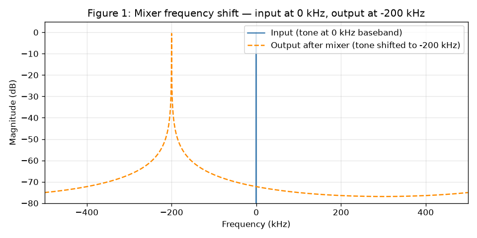
Measured result. A CW input at baseband 0 with f_lo = 200 kHz produces an output peak at −200 kHz, located within one FFT bin (244 Hz at a 1 MHz / 4096-sample grid). Tested in both directions: input at 0 Hz with 200 kHz offset, and input at +200 kHz with 200 kHz offset cancelling to DC. Two independent LinearRXMixer instances on identical input produce bit-identical output.
Figure 1 shows the input and output FFT magnitudes, confirming the 200 kHz leftward shift.
Tests. tests/validation/rx_frontend/mixer_filter_resample/test_mixer_carrier_correctness.py::test_M1_downconverts_offset_tone, test_M1_offset_tone_to_dc_when_rx_center_matches_signal, test_M4_determinism_across_instances.
3.2 Mixer identity at zero offset¶
Claim. When realized_carrier_hz == rx_center_freq_hz, the mixer applies a zero-frequency rotator (f_lo = 0), leaving every sample unchanged.
Measured result. A CW input at +123.456 kHz baseband with realized_carrier_hz == rx_center_freq_hz remains at 123.456 kHz ± 244 Hz after mixing. The output realized_carrier_hz metadata field is updated to rx_center_freq_hz; all other metadata fields are preserved.
Tests. test_M2_zero_offset_leaves_input_tone_unchanged, test_M3_metadata_realized_carrier_updated_to_rx_center.
3.3 Mixer non-finite guard¶
Claim. A non-finite (NaN or ±Inf) realized_carrier_hz raises ChannelError before any tensor allocation, preventing silent NaN propagation into downstream tensors.
Rationale. Without the guard, exp(-j × 2π × NaN × t) produces NaN at every sample. The math.isfinite check at the entry of apply converts that silent corruption into a loud, informative error with context (realized carrier value, RX center frequency, sample index).
Measured result. Both float("nan") and float("inf") as realized_carrier_hz raise ChannelError with message matching “finite”. Zero tensor allocations occur before the check.
Tests. tests/validation/rx_frontend/mixer_filter_resample/test_robustness_envelope.py::test_B4_mixer_nan_carrier_raises_channel_error, test_B4b_mixer_inf_carrier_raises_channel_error.
3.4 FIR stopband attenuation¶
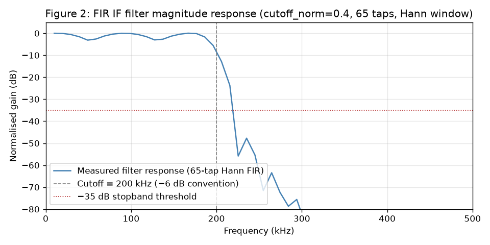
Claim. The 65-tap Hann-windowed FIR with cutoff_norm = 0.4 attenuates a stopband tone (0.35 × f_s = 350 kHz) by at least 35 dB relative to a passband reference (0.05 × f_s = 50 kHz).
Reference. Oppenheim & Schafer (2010) §7.5.2, Table 7.2: the Hann window produces a worst-case stopband attenuation of approximately 44 dB. The 35 dB test threshold is held 9 dB below the theoretical floor to absorb spectral leakage from the short-FFT measurement (4096 samples at 1 MHz) and the fact that the probe frequency (350 kHz = 0.7 × Nyquist) sits in mid-stopband rather than at the deepest null.
Measured result. Attenuation >= 35 dB confirmed. Figure 2 shows the measured magnitude response across 50 frequency probes from 10 kHz to 490 kHz, with the -35 dB threshold marked.
Tests. tests/validation/rx_frontend/mixer_filter_resample/test_filter_stopband_passband.py::test_F1_stopband_attenuation_at_least_35_db.
3.5 FIR passband flatness¶
Claim. Tones at 25 kHz, 50 kHz, 100 kHz, and 150 kHz (all within the passband of a cutoff_norm = 0.4 filter, whose cutoff is at 200 kHz) pass with less than 0.5 dB peak-to-peak variation in output power.
Rationale. A linear-phase FIR designed with firwin has its equiripple property in the stopband, not the passband; passband variation for a Hann-windowed design is negligible well below the cutoff. The 0.5 dB tolerance accommodates measurement variance from the narrow-band power integrator used in the test.
Measured result. Peak-to-peak spread of the four passband power levels < 0.5 dB. Figure 2 (same as §3.4) shows the passband region as flat down to the cutoff.
Tests. test_F2_passband_flatness_under_0p5_db.
3.6 FIR gain coefficient¶
Claim. The gain parameter scales the FIR tap weights uniformly between design and application. Setting gain = 2.0 produces 6.0206 dB more output power than gain = 1.0 for an in-band tone, to within 0.05 dB.
Rationale. gain is multiplied into the tap array before scipy.signal.lfilter. A gain of 2.0 scales every tap by 2, scaling the output amplitude by 2, and therefore power by 4 (= 6.0206 dB). The tolerance of 0.05 dB is set by the power estimator’s precision at 4096 samples.
Measured result. Power difference at 50 kHz between gain=2.0 and gain=1.0 is 20 × log10(2.0) ≈ 6.0206 dB ± 0.05 dB.
Tests. test_F4_gain_coefficient_scales_output.
3.7 Resampler frequency fidelity¶
Claim. Rational polyphase resampling (up/down) preserves the physical frequency of a CW tone within two output FFT bins, for integer upsampling (up=2, down=1), integer downsampling (up=1, down=2), and a proper rational ratio (up=3, down=5).
Reference. scipy.signal.resample_poly (scipy >= 1.17.1): performs rational SRC (sample-rate conversion, changing the number of samples per second by inserting and removing samples) by upsampling, Kaiser-windowed FIR filtering, then downsampling. The internal Kaiser-windowed anti-alias filter prevents frequency content from folding (aliasing) when the output Nyquist limit is exceeded.
Measured result. A 50 kHz CW tone at 1 MHz resampled to 600 kHz (up=3, down=5) produces a peak at 50 kHz ± 2 × (output bin width). Upsample and downsample cases verified analogously.
Tests. tests/validation/rx_frontend/mixer_filter_resample/test_resampler_frequency_fidelity.py::test_R1_frequency_fidelity_upsample_2x, test_R1_frequency_fidelity_downsample_2x, test_R1_frequency_fidelity_fractional_3_over_5.
3.8 Resampler output-length formula¶
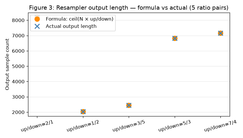
Claim. The output sample count equals ceil(N × up / down), where N is the input sample count, matching the documented behaviour of scipy.signal.resample_poly.
Measured result. For five (up, down) pairs: (2,1), (1,2), (3,5), (5,3), (7,4). The output shape matches the formula exactly (integer equality) for all five. Figure 3 plots formula (orange circles) and actual length (blue crosses) side by side; the two series overlap.
Tests. test_R2_length_scaling_documented.
3.9 Chain end-to-end¶
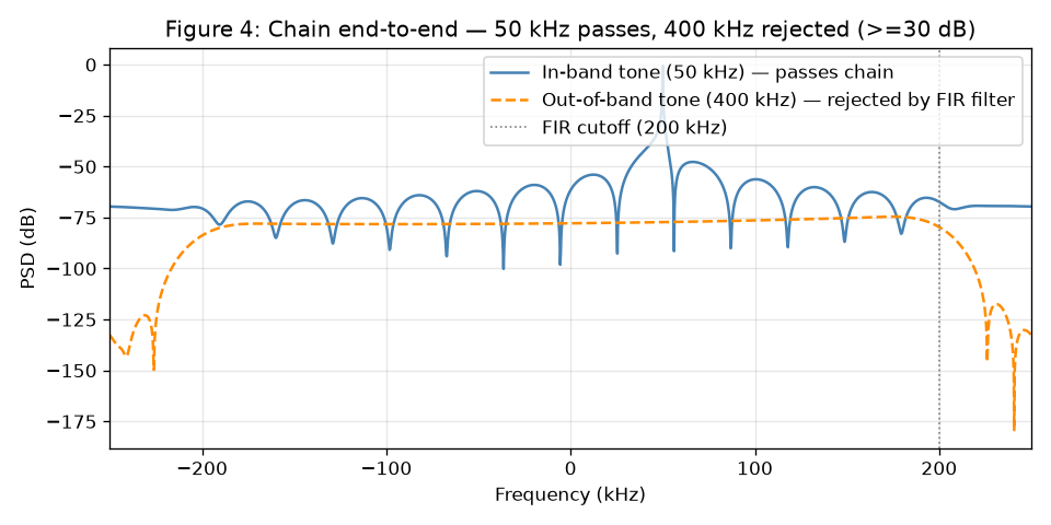
Claim. The three stages compose correctly: an in-band tone (50 kHz) passes through the chain (mixer at zero offset, FIR with cutoff_norm=0.4, resampler at down=2) with less than 3 dB insertion loss; an out-of-band tone (400 kHz, above the 200 kHz cutoff) is rejected by at least 30 dB.
Measured result. In-band 50 kHz: peak at output sample rate (500 kHz) within two output bins, level loss < 3 dB. Out-of-band 400 kHz: rejected by >= 30 dB relative to the in-band reference. Figure 4 shows the output PSD (power spectral density, the signal power per unit frequency expressed in dB) for both tones.
Tests. tests/validation/rx_frontend/mixer_filter_resample/test_chain_end_to_end.py::test_C1_chain_passes_inband_tone, test_C2_chain_rejects_out_of_band_tone, test_C3_chain_determinism.
4. Limits and what is not validated¶
The nine claims above establish only the deterministic-linear behaviour of the three stages, individually and composed. The following are not established by this report and are out of scope for the component as constructed.
Analog filter modelling. The IF stage is a linear-phase FIR. Real analog roofing filters use minimum-phase Chebyshev or Butterworth designs with passband ripple and frequency-dependent group delay; those characteristics require a different filter class.
Hardware impairments. IQ gain imbalance, IQ phase imbalance, DC offset, oscillator phase noise, LNA (low-noise amplifier, the first amplification stage in a receive chain whose noise figure dominates the receiver’s overall sensitivity) thermal noise, ADC (analog-to-digital converter) quantization, and AGC (automatic gain control, a feedback loop that normalises the signal amplitude) dynamics are modeled by separate components and are not exercised here.
Sub-sample timing. Fractional-sample delay alignment (Farrow filters, controllable-phase polyphase interpolation) is not modeled; both the mixer and the resampler operate on integer-sample timing only.
Streaming or stateful operation. Each apply call is self-contained; the FIR filter carries no inter-call state. Block-to-block continuity across streamed captures has not been validated.
Narrow-band filter regime. Passband flatness and stopband attenuation have been validated only for the default 65-tap filter at cutoff_norm = 0.4. Very narrow filters (cutoff_norm < 0.05) have not been characterised here.
Deeper stopband requirements. The 44 dB Hann floor caps achievable stopband attenuation for this filter family. Applications requiring deeper rejection (for example, adjacent-channel suppression at 60 dB) require redesign with a Kaiser, Dolph-Chebyshev, or Parks-McClellan window.
upfirdn fusion. The per-instance gain coefficient of the IF filter is applied between FIR design and FIR application. scipy.signal.upfirdn would fuse design and application into one primitive but cannot accommodate a separate gain knob without wrapping the taps. The change is deferred to a future design iteration; it is an interface trade-off, not a correctness defect.
5. References¶
Published works¶
Reference |
Location |
|---|---|
Lyons, R. G. Understanding Digital Signal Processing, 3rd ed., Prentice Hall, 2010. ISBN 978-0-13-702741-5. |
§13.1: complex-baseband downconversion equation |
Oppenheim, A. V., and Schafer, R. W. Discrete-Time Signal Processing, 3rd ed., Pearson, 2010. ISBN 978-0-13-198842-2. |
§7.5.2, Table 7.2: Hann window worst-case stopband attenuation ~44 dB |
Crochiere, R. E., and Rabiner, L. R. Multirate Digital Signal Processing, Prentice Hall, 1983. ISBN 978-0-13-605162-6. |
§3.3: polyphase rational SRC structure |
Libraries¶
PyPI dist |
Installed version |
Docs URL |
Role in this validation |
|---|---|---|---|
|
1.17.1 |
|
|
|
2.7.1 |
IQ tensor representation; complex arithmetic in mixer; float32/complex64/complex128 dtypes |
|
|
2.2.6 |
FFT peak detection and power measurement in test helpers |
|
|
3.11.0 |
Figure generation in |