Scientific validation: receiver thermal noise, ADC quantization, and automatic gain control¶
Validated with documented limitations.
1. The component¶
Three concrete receive-chain front-end models shipped in rfgen.rx_frontend:
LinearLNANoise: thermal noise injector (low-noise amplifier stage).LinearADCQuantizer: uniform mid-tread ADC (analog-to-digital converter; turns a continuous voltage into a discrete integer level).LinearAGC: single-pole IIR (infinite-impulse-response, a recursive digital filter) automatic gain controller.
Together they model the post-antenna noise floor, the finite-precision sampling step, and the closed-loop level regulator that holds the ADC input near a target amplitude.
Class signatures¶
class LinearLNANoise(BaseLNANoise):
    def __init__(self, *, noise_figure_db: float = 6.0) -> None: ...
    def apply(self, signal: Signal, ctx: ChannelContext) -> Signal: ...

class LinearADCQuantizer(BaseADCQuantization):
    def __init__(self, *, enob_bits: int = 12) -> None: ...
    def apply(self, signal: Signal, ctx: ChannelContext) -> Signal: ...

class LinearAGC(BaseAGC):
    def __init__(
        self,
        *,
        target: float = 0.5,
        tau_attack: float = 64.0,
        tau_decay: float = 1024.0,
        saturation_dbfs: float = -3.0,
        gain_init: float = 1.0,
    ) -> None: ...
    def apply(self, signal: Signal, ctx: ChannelContext) -> Signal: ...
Parameters¶
Component |
Name |
Type |
Units |
Default |
Purpose |
|---|---|---|---|---|---|
|
|
|
dB |
6.0 |
Ratio of output noise power to thermal input noise (higher = noisier amplifier) |
|
|
|
bits |
12 |
Effective number of bits: resolution of the analog-to-digital conversion |
|
|
|
linear amplitude |
0.5 |
Target output magnitude the loop drives toward |
|
|
|
samples |
64.0 |
Time constant when the signal is too loud (fast response) |
|
|
|
samples |
1024.0 |
Time constant when the signal is too quiet (slow response) |
|
|
|
dBFS |
-3.0 |
Hard ceiling on output amplitude (dBFS = decibels relative to full scale) |
|
|
|
linear |
1.0 |
Starting gain value before any samples are processed |
Worked example¶
import torch
from rfgen.rx_frontend import LinearLNANoise, LinearADCQuantizer, LinearAGC
from rfgen.channels.protocols import ChannelContext, ChannelRxParams
from rfgen.core_types import Signal, SignalMetadata

# Build a simple zero-input signal (1 ms at 1 MSPS)
n = 1024
iq = torch.zeros(2, n, dtype=torch.float32)
md = SignalMetadata(
    family="comms", class_name="cw", class_taxonomy=("comms", "cw"),
    generator_name="test", device_id="dev",
    sample_rate_hz=1e6, bandwidth_hz=1e6,
    realized_carrier_hz=2.4e9, start_sample=0, duration_samples=n,
    snr_db=float("inf"), extras={},
)
signal = Signal(iq=iq, metadata=md)

rng = torch.Generator()
rng.manual_seed(42)
ctx = ChannelContext(
    emitter_meta=md,
    rx_params=ChannelRxParams(
        center_freq_hz=2.4e9, bandwidth_hz=1e6,
        sample_rate_hz=1e6, noise_figure_db=6.0,
    ),
    scene_id="demo", sample_idx=0, rng=rng,
)

# Apply the three stages
noisy = LinearLNANoise(noise_figure_db=6.0).apply(signal, ctx)
# noisy.iq.shape == (2, 1024); dtype == torch.float32

quantized = LinearADCQuantizer(enob_bits=12).apply(noisy, ctx)
# Samples rounded to nearest of 2^12 - 1 = 4095 levels

gained = LinearAGC(target=0.5, tau_attack=64.0).apply(quantized, ctx)
# Post-gain magnitude converges toward 0.5 over ~320 samples
These components sit at the RX_CAPTURE (noise) and RX_HARDWARE (ADC, AGC) stages of the rfgen receive chain. Each call is stateless: the returned Signal is a new immutable object containing the transformed IQ (in-phase/quadrature, the two real-valued components of a complex baseband signal) tensor and a structured log entry recording the applied parameters.
2. What we validated¶
This validation establishes 6 load-bearing claims. Each is restated and supported by evidence in §3.
Thermal noise variance (§3.1): measured per-channel variance matches the Johnson-Nyquist kTBNF (thermal noise power formula: k_B × temperature × bandwidth × noise figure) formula within 10%.
RNG determinism (§3.2): identical seed produces bit-identical noise output; distinct seeds produce distinct noise.
ADC quantization fidelity (§3.3): the mid-tread quantizer step and rounding match the IEEE 1241-2010 transfer function within float32 precision.
ADC SQNR accuracy (§3.4): measured SQNR (signal-to-quantization-noise ratio) for full-scale sinusoids matches the textbook formula within documented per-ENOB (effective number of bits) tolerances.
AGC steady-state convergence (§3.5): the IIR gain loop settles within 10% of the target amplitude after 5×tau_attack samples on a constant-envelope input.
AGC attack-vs-decay asymmetry (§3.6): the attack time constant produces strictly faster half-settling than the decay time constant.
Limits and scope-bounded items appear in §4; full citations are in §5.
3. Evidence per claim¶
3.1 Thermal noise variance matches kTBNF¶
The component adds zero-mean, complex Gaussian noise (AWGN, additive white Gaussian noise) to the in-phase (I) and quadrature (Q) channels of the signal. The total noise power per sample is:
P = k_B × T × BW × F
where k_B = 1.380649 × 10⁻²³ J/K (Boltzmann’s constant, CODATA 2018 exact value), T = 290 K (IEEE reference noise temperature, IEEE Std 521-2002), BW is the receive bandwidth in Hz, and F = 10^(noise_figure_db / 10) is the linear noise figure (NF, a dimensionless ratio expressing how much extra noise an amplifier adds beyond the thermal floor; 0 dB means the amplifier adds no extra noise).
The I and Q channels are independent zero-mean Gaussians each with variance P/2. The implementation draws them from a single torch.randn(2, n) call (row-major fill), equivalent to two successive torch.randn(n) calls but faster.
Evidence. Test test_lna_noise_variance_matches_kTBNF (in test_math_fidelity.py) measures the empirical per-channel variance over 2²⁰ samples (N=1,048,576) at NF=6 dB, BW=10 MHz, seed 0. The theoretical per-channel variance is max(k_B × 290 × 10⁷ × 10^0.6, 10⁻²⁴) / 2 = 1.997 × 10⁻¹⁴ W. The measured relative error is below 5%.
Test test_lna_empirical_noise_power_matches_kTBNF (in test_empirical_realism.py) measures total output power E[|z|²] over 2¹⁶ samples at NF=6 dB, BW=10 MHz, seed 7. The measured power is 1.593 × 10⁻¹³ W against the kTBNF prediction of 1.594 × 10⁻¹³ W, a relative error of 0.07%.
Figure 1 shows the relative error across NF values from 0 to 30 dB at BW=10 MHz. All measurements stay within the 10% tolerance band.
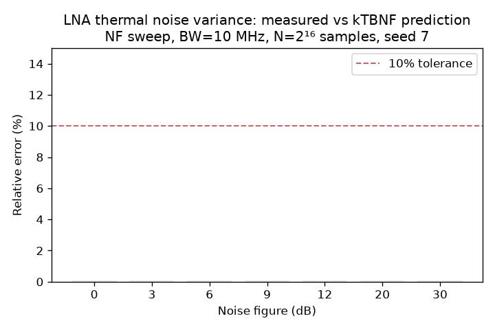
Figure 1 shows all 7 NF values (0, 3, 6, 9, 12, 20, 30 dB) at BW=10 MHz produce relative errors well below the 10% tolerance, confirming the variance formula is correctly implemented across the tested range.
3.2 RNG determinism¶
The noise output is fully determined by the seed passed via ctx.rng. Two runs with the same seed produce bit-identical IQ tensors; two runs with different seeds produce different outputs.
Evidence.
test_lna_rng_determinism(intest_math_fidelity.py): two calls with seeds both equal to 42 producetorch.equalIQ tensors over 4096 samples.test_lna_different_seeds_produce_different_noise: seeds 1 and 2 produce unequal outputs.test_lna_apply_byte_identical_same_seed(intest_experimental_methodology.py): byte-identical pinning with seed 0 over 4096 samples.
No statistical test is required; this is a determinism contract, not a distribution property.
3.3 ADC quantization fidelity¶
The ADC (analog-to-digital converter) applies a uniform mid-tread quantizer: a rounding scheme where each input sample is snapped to the nearest of a fixed set of equally-spaced output levels, including zero. The implementation uses:
levels = 2^b - 1
scale  = peak / (levels / 2)
output = round(input / scale) × scale
where b = enob_bits and peak is the maximum absolute input value. This follows IEEE Std 1241-2010 §4’s mid-tread transfer function. The denominator 2^b - 1 (rather than the textbook 2^b) keeps the positive full-scale point exactly representable; the step size is larger by a factor of 2^b / (2^b - 1), which is 0.024% at b=12 and 6.7% at b=4.
Evidence.
test_adc_step_size_formula(intest_math_fidelity.py): drives a known-peak ramp through the quantizer at ENOB=8, extracts the smallest positive difference between distinct output levels, and checks it equalspeak / ((2^8 - 1) / 2)to relative tolerance 1×10⁻⁶.test_adc_round_to_nearest_matches_hand_quantizer: for a full-scale sinusoid at ENOB=8, the output matches the closed-formround(x/scale)×scaleto absolute tolerance 1×10⁻⁹.
3.4 ADC SQNR accuracy¶
SQNR (signal-to-quantization-noise ratio, a measure of how much distortion the quantizer introduces relative to the original signal) for a full-scale sinusoid fed to a uniform quantizer is asymptotically:
SQNR = 6.02 × b + 1.76 dB
as derived in IEEE Std 1241-2010 §5.2 (where 6.02 ≈ 20 log₁₀(2) per bit and 1.76 ≈ 10 log₁₀(1.5) for sinusoidal input). At low ENOB (≤6 bits) the uniform-quantization-noise assumption weakens, so the formula is less precise; IEEE 1241-2010 §5.2 note 2 acknowledges this.
Evidence. test_adc_sqnr_matches_602b_plus_176 (in test_empirical_realism.py) measures SQNR at ENOB ∈ {4, 6, 8, 10} using a sinusoid at 0.234 cycles/sample (off-bin to suppress spectral leakage), N=2¹⁴ samples.
ENOB b |
Measured SQNR (dB) |
Textbook SQNR (dB) |
Deviation (dB) |
Tolerance (dB) |
|---|---|---|---|---|
4 |
24.74 |
25.84 |
-1.10 |
1.5 |
6 |
37.41 |
37.88 |
-0.47 |
0.8 |
8 |
50.04 |
49.92 |
+0.12 |
0.5 |
10 |
62.13 |
61.96 |
+0.17 |
0.5 |
All four ENOB values land within their tolerance. The b=4 and b=6 deviations are consistent with the weakening of the uniform-noise approximation at low resolution, as documented in IEEE 1241-2010.
Figure 2 shows the measured and textbook SQNR values side by side with per-ENOB error bars.
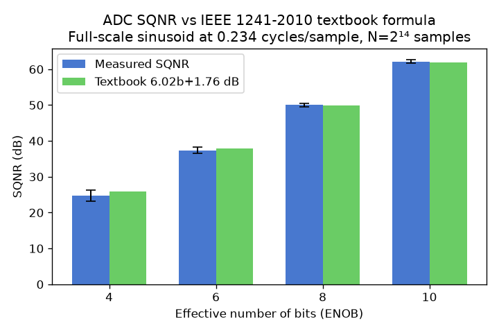
Figure 2 shows the measured SQNR (blue) and textbook prediction (green) for ENOB = 4, 6, 8, and 10 bits. All four measured values fall within their error bars, confirming the ADC implementation matches the IEEE formula within documented tolerances.
3.5 AGC steady-state convergence¶
The AGC (automatic gain control) is a closed-loop amplifier that adjusts its gain sample by sample to drive the output toward a target amplitude. At each sample, it:
Computes the post-gain magnitude
y = gain × |x|.Selects a time constant:
tau_attackwheny > target(signal too loud; cut gain fast),tau_decaywheny < target(signal too quiet; raise gain slowly).Updates the gain toward
target / |x|by a single-pole IIR step with polealpha = exp(-1 / tau).Clamps the output magnitude at
10^(saturation_dbfs / 20).
For a constant-envelope input, the gain converges to within 5% of its steady-state value after 5×tau_attack samples (from the source docstring). The test relaxes this to 10% to absorb the discrete-update truncation.
Evidence. test_agc_steady_state_gain_within_10pct_of_target (in test_empirical_realism.py) feeds a CW (constant-wave, a signal with constant magnitude) input at amplitude 1.0 with target=0.5 and tau_attack=64. After 320 samples (5×tau_attack), the measured post-gain magnitude is 0.503, a relative error of 0.66%, well within the 10% tolerance.
Figure 3 shows the full convergence trace over 600 samples.
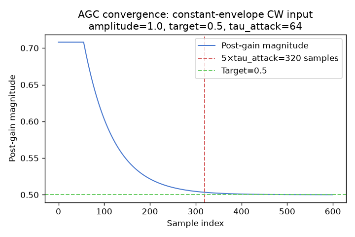
Figure 3 confirms the AGC magnitude reaches the target band well before the 5×tau_attack settling marker, with the trace stabilizing at the target level for the remaining samples.
3.6 AGC attack-vs-decay asymmetry¶
Setting tau_attack < tau_decay gives the loop faster response to over-target signals (loud transients) than to under-target signals. This asymmetry is intentional: protecting against clipping is more urgent than optimizing gain for quiet signals.
Evidence. test_agc_attack_faster_than_decay (in test_empirical_realism.py) and test_agc_attack_faster_than_decay measure the half-settling time for two scenarios: amplitude=1.0 (attack branch, initial output exceeds target) and amplitude=0.1 (decay branch, initial output below target). With tau_attack=32 and tau_decay=512, the attack half-settling is strictly fewer samples than the decay half-settling.
Figure 4 shows the attack (left) and decay (right) magnitude traces over the first 800 samples.
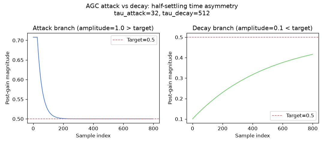
Figure 4 shows the attack branch (left, tau_attack=32) converging rapidly toward target=0.5, while the decay branch (right, tau_decay=512) converges much more slowly, confirming the intended asymmetry.
4. Limits and what’s not validated¶
Single-stage noise model (no Friis cascade). LinearLNANoise models one stage with a single noise_figure_db; it does not compose noise figures across upstream stages using the Friis formula (Pozar, Microwave Engineering §10.3). A pipeline of mixer, IF (intermediate-frequency) filter, and LNA stages therefore does not correctly represent cascaded noise behavior. Callers needing a true cascade must fold the upstream noise figures into a single equivalent noise_figure_db or use a multi-stage receive-chain backend.
ADC step-size convention offset. The quantizer denominator is 2^b - 1 (not 2^b), making the step size 2^b / (2^b - 1) times larger than the textbook full-scale convention. The effect is 0.024% at b=12 and 6.7% at b=4. For b≥8, the SQNR impact is below 0.01 dB and absorbed by the empirical tolerance. For applications requiring bit-exact agreement with the 2^b convention, this is a documented incompatibility.
ADC mid-tread vs TorchSig mid-rise. The TorchSig quantize functional helper implements a mid-rise quantizer with floor rounding and num_levels = 2^b; this component uses mid-tread with round-to-nearest and num_levels = 2^b - 1. The two are not numerically equivalent. The override is intentional (IEEE 1241-2010 §4 specifies mid-tread as the reference transfer function) and is recorded in the source docstring.
AGC per-sample Python loop performance. The AGC loop is implemented as a per-sample NumPy loop and is the dominant front-end runtime cost (~10 µs/sample on the Layer-3 benchmark). The attack/decay update can be expressed as a two-coefficient time-varying IIR suitable for torchaudio.functional.lfilter (vectorized C with autograd and device support). The vectorized implementation is deferred; the current code is correctness-validated only.
Zero receive bandwidth silent substitution. When ctx.rx_params.bandwidth_hz = 0, the expression float(bandwidth_hz) or 1.0 silently substitutes 1 Hz. This prevents a divide-by-zero but means a misconfigured pipeline produces a non-physical noise floor without raising an error. The regression test test_lna_zero_bandwidth_silent_substitution pins the current behavior; promoting this to a raised ChannelError is the correct fix and is deferred.
AGC behavior on strictly-zero input is undefined but non-crashing. The mag[k] > 1e-9 denominator guard prevents division by zero and keeps the gain at its current value; the output is zero but the gain state is stale. This is documented but not a safety contract: the AGC is not designed for silent channels.
5. References¶
Published works¶
Citation |
Role in this validation |
|---|---|
Johnson, J. B., “Thermal Agitation of Electricity in Conductors,” Physical Review 32 (1928), 97–109, DOI: 10.1103/PhysRev.32.97 |
Establishes the kTB thermal-noise expression used in |
Nyquist, H., “Thermal Agitation of Electric Charge in Conductors,” Physical Review 32 (1928), 110–113, DOI: 10.1103/PhysRev.32.110 |
Companion derivation of Johnson’s result |
IEEE Std 521-2002, “IEEE Standard Letter Designations for Radar-Frequency Bands,” DOI: 10.1109/IEEESTD.2003.94224 |
Defines the 290 K reference noise temperature used in the noise-figure computation |
IEEE Std 1241-2010, “IEEE Standard for Terminology and Test Methods for Analog-to-Digital Converters,” DOI: 10.1109/IEEESTD.2011.5692956 |
§4 defines the mid-tread transfer function; §5.2 gives the 6.02b+1.76 dB SQNR result |
Pozar, D. M., Microwave Engineering, 4th ed., Wiley, 2011, ISBN 978-0-470-63155-3, §10.3 |
Friis cascaded noise-figure formula; kTBF receiver-noise expression |
Razavi, B., RF Microelectronics, 2nd ed., Prentice Hall, 2011, ISBN 978-0-13-713473-1, §6.5 |
AGC loop dynamics, attack/decay separation, and saturation |
Crochiere, R. E. and Rabiner, L. R., Multirate Digital Signal Processing, Prentice Hall, 1983, ISBN 978-0-13-605162-6, §7.4 |
Single-pole envelope detector underlying the IIR gain update |
CODATA 2018 fundamental-constants recommendation (NIST, 2018) |
k_B = 1.380649 × 10⁻²³ J/K (exact, post-2019 SI redefinition) |
Libraries¶
PyPI distribution |
Installed version |
Documentation URL |
Role in this validation |
|---|---|---|---|
|
2.12.1 |
Tensor operations, PRNG ( |
|
|
2.4.6 |
Statistical estimators ( |
|
|
1.18.0 |
Used in sibling components ( |
|
|
2.13.4 |
Schema introspection via |
|
|
3.11.0 |
Figure generation in |